
Vacuum Lifter Support System: Jib Cranes, Articulated Arms, Overhead Rails and Mobile Bases
A vacuum lifter support system is the structure that carries the vacuum tube lifter and allows the operator to move the suspended load through the required working area. Although the vacuum generator, lifting tube and suction head determine how the load is gripped and lifted, the support structure determines where the lifter can actually travel.
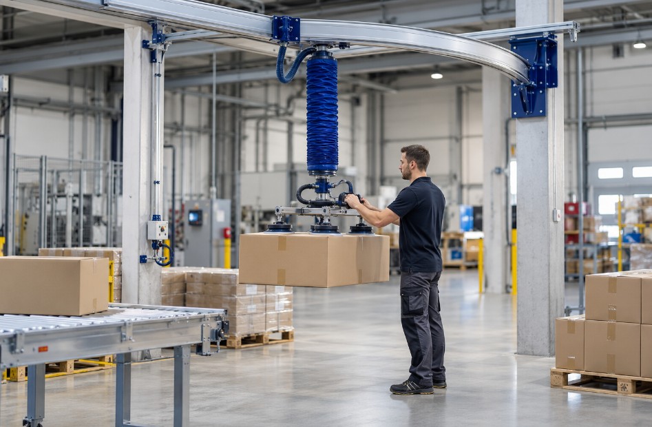
This makes the support system a fundamental part of the complete vacuum lifting installation. A correctly selected support structure should provide the required horizontal reach, sufficient suspension height, stable movement and suitable integration with the production or warehouse layout.
Typical configurations include jib cranes, articulated arms, lightweight overhead rail systems and mobile self-supporting bases. In some installations, a vacuum tube lifter can also be suspended from an existing crane structure if the available height and structural conditions are suitable.
This guide explains how to select a vacuum lifter support system, which parameters should be defined before installation and how the support structure interacts with lifting height, working area, operator movement and the complete vacuum handling process.
For a broader explanation of how vacuum tube lifters work, see our Vacuum Tube Lifters Technical Overview.
Why the Vacuum Lifter Support System Matters
A vacuum tube lifter does not operate independently in space. The lifter must be suspended from a structure capable of supporting the equipment and allowing controlled horizontal movement.
The vacuum lifter support system therefore influences several practical characteristics of the installation:
- the horizontal working area;
- the maximum and minimum pickup positions;
- the available lifting height;
- operator access to pallets, machines and conveyors;
- the direction in which loads can be moved;
- the amount of structural modification required;
- whether the installation is fixed or mobile;
- how naturally the operator can guide the load.
Selecting the vacuum lifter first and considering the support structure afterwards can create unnecessary limitations. The better approach is to evaluate the complete handling process from the beginning.
Load weight, suction area and lifting capacity are still important, but they represent only one part of the system. The required reach, suspension height and workstation geometry must also be known before a complete configuration can be defined.
Start With the Required Working Area
The first step when selecting a vacuum lifter support system is to define where the load needs to travel.
Start with the pickup point and the destination. Then consider every position that the load must pass through between them.
Useful questions include:
- Where is the product picked up?
- Where is it placed?
- How far must it travel horizontally?
- Does the operator move around a single workstation or along a production line?
- Must the lifter reach several pallets or machines?
- Are there columns, walls, racks or other obstacles?
- What is the lowest pickup height?
- What is the highest placement point?
- How much clear height is available above the working area?
The answers help determine whether the application is best served by a rotating jib crane, an articulated arm, a linear overhead system or a mobile support structure.
Work-area dimensions are also part of the technical information required when sizing a vacuum tube lifter. For a complete sizing process, see our Vacuum Tube Lifter Capacity guide.
1. Jib Crane as a Vacuum Lifter Support System
A jib crane is one of the most common ways to support a vacuum tube lifter. The lifting device is suspended from a horizontal boom that rotates around a fixed support point.
This creates a circular or partial-circular working area around the column or mounting point.
A jib crane can be a suitable vacuum lifter support system when the operator repeatedly transfers loads between several positions located within the same general workstation.
Typical examples include:
- moving cartons from a conveyor to a pallet;
- loading or unloading a machine;
- moving bags between a production line and storage position;
- handling panels around a fixed processing station;
- palletizing loads within a defined radius.
Floor-mounted jib crane
A floor-mounted jib crane uses its own column and foundation or anchoring point. This can provide a clearly defined working area without depending on the building structure for the main support location.
When planning this type of vacuum lifter support system, the column position is important because it affects both reach and operator access. The support should not create an obstacle in the same path that the operator or load must use.
Column-mounted support
Where the existing building structure permits it, support systems can also be connected to an existing structural column. This may reduce the amount of floor space occupied by the lifting installation.
The suitability of the existing structure must still be checked before installation. The support point must be appropriate for the loads and reaction forces generated by the handling system.
When a jib crane works well
A jib crane is particularly useful where most movements take place around a central point and the required working radius is clearly defined.
If the operator must move loads over a long straight distance, however, an overhead rail or gantry-type system may provide a more suitable movement pattern.
2. Articulated Arm Support Systems
An articulated arm uses multiple pivot points instead of a single rigid rotating boom. This allows the suspended lifter to move through a more flexible path around the workstation.
As a vacuum lifter support system, an articulated arm can be useful where the operator must reach around equipment, work inside a more restricted layout or access positions that would be inconvenient with a conventional straight jib.
The additional articulation changes the movement geometry. Instead of following only one rotation around a central axis, the arm can fold and extend through several positions.
This can be useful where:
- the workstation contains obstacles;
- machines restrict direct access;
- the operator needs flexible reach around a production cell;
- the installation has limited floor space;
- a compact parked position is desirable.
The correct solution depends on the actual layout. An articulated arm should not be selected simply because it offers greater movement flexibility. The complete path of the load should still be mapped before the support system is defined.
3. Overhead Rail and Lightweight Gantry Systems
Where loads must travel over a larger or more linear working area, an overhead rail system can provide an effective vacuum lifter support system.
Instead of rotating around one fixed point, the lifter moves along a rail or bridge structure. This allows the working area to extend across a production line, warehouse zone or larger workstation.
Adria Manipulatorji uses overhead crane configurations for industrial handling applications where extended coverage and flexible movement are required. These systems can be configured with fixed or moving rails depending on the required handling path.
Single-axis movement
A simple monorail arrangement provides travel along one primary direction. This can be appropriate where the load is repeatedly moved along the same linear route.
For example, a product may be picked up at one end of a workstation and placed farther along the production process.
Two-dimensional working area
A bridge or lightweight overhead crane arrangement can provide movement in more than one horizontal direction. This creates a rectangular working area rather than the circular coverage typically associated with a jib crane.
This type of vacuum lifter support system can be useful where the operator needs access to several pallets, machines or storage positions spread across a wider area.
Advantages of overhead installation
Moving the main supporting structure above the working area can reduce the number of obstructions at floor level. This is particularly useful where forklifts, carts, pallets or operators must move freely through the same space.
The trade-off is that the installation must be compatible with the available building height and structural support conditions.
4. Mobile Vacuum Lifter Support Systems
Not every vacuum tube lifter needs to remain permanently installed at one workstation.
A vacuum lifter support system can also be mounted on a self-standing mobile base. Tube Lifters describes configurations where the support crane is mounted on a forkable base that can be moved with a forklift or pallet truck.
This approach can be useful where the same lifting equipment is required in different production zones at different times.
Applications may include:
- seasonal handling operations;
- production areas that change according to batch or product;
- warehouses with several temporary handling stations;
- food-processing areas where equipment must be repositioned;
- facilities where permanent structural installation is undesirable.
A practical example is a food-industry vacuum tube lifter installed on a stainless-steel jib crane with a self-standing forkable base. The complete handling station can be relocated when the production flow changes.
Mobility should still be planned carefully. The base must provide the required support during operation, and the available space must accommodate both the support structure and the movement of the load.
5. Can a Vacuum Tube Lifter Be Installed on an Existing Crane?
In some facilities, an existing crane or support structure may already be available. It can therefore be tempting to suspend the vacuum tube lifter directly from that system.
This can be possible, but the existing crane must first be evaluated for compatibility with the complete vacuum lifter support system.
One of the most important issues is suspension height. Vacuum tube lifters require vertical space for the lifting tube and operating movement, which means they can require a higher suspension point than a conventional hoist.
Before using an existing crane, check:
- available suspension height;
- required minimum pickup position;
- required maximum placement height;
- structural capacity;
- available horizontal travel;
- interaction with existing crane equipment;
- whether the vacuum lifter can move without side pulling or interference.
An existing crane may be structurally strong enough but still unsuitable if the hook or suspension point is too low for the required vertical working range.
6. Suspension Height and Vertical Working Range
Height is one of the most frequently overlooked parameters when designing a vacuum lifter support system.
The required vertical space is influenced by the lifting tube, control unit, suction head and the dimensions of the load itself.
The designer therefore needs to understand both extremes of the process:
- the lowest position where the suction head must reach the product;
- the highest position where the load must be placed.
Typical examples include picking a carton from near floor level and stacking it high on a pallet, or removing a product from a conveyor and positioning it inside a machine.
Ceiling height alone does not describe the available working space. Beams, ventilation systems, lighting, cable trays and other overhead equipment can reduce the usable suspension height.
For this reason, clear-height restrictions should be documented during the initial application review.
7. Horizontal Forces and Side Loading
A vacuum tube lifter is primarily designed to lift the load vertically while the support structure provides the horizontal movement.
This distinction is important when designing the vacuum lifter support system.
The operator should not need to drag the suspended lifter sideways by pulling strongly against the lifting tube. The support structure should allow the lifting point to move naturally with the load.
Excessive side loading can introduce:
- torsion in the lifting tube;
- off-centre loading;
- additional stress on the suction interface;
- more difficult operator control;
- unnecessary wear.
The working area should therefore be arranged so that the support trolley, arm or crane can follow the operator through the complete handling cycle.
This is also why the position of the support system is just as important as its theoretical reach.
8. Reaction Forces, Anchoring and Structural Integration
Every vacuum lifter support system transfers forces into its supporting structure.
For a floor-mounted jib crane, these forces are transferred through the column and its anchoring arrangement. For a column-mounted arm, they are transferred into the existing building structure. For an overhead system, they are carried through rails, supports and the surrounding structure.
Before installation, the structural arrangement should therefore be checked for:
- required load capacity;
- anchoring conditions;
- support stiffness;
- acceptable movement or deflection;
- interaction with the surrounding building structure.
The exact structural design depends on the installation and must be evaluated for the real support conditions.
This part of the project should not be treated as an accessory decision after the vacuum lifter has already been selected. The support system is part of the load path of the complete installation.
9. Routing the Vacuum Supply Through the Support System
The vacuum lifter support system must also allow the required hoses, pipes, electrical cables or compressed-air lines to reach the lifting device without interfering with movement.
The vacuum source may be positioned separately from the lifting point. Tube Lifters specifies that the location of the vacuum pump relative to the start of the crane or jib system should be considered during installation, and applications requiring longer distances should be reviewed with the supplier.
Routing should allow the support arm or trolley to move through its full working area without:
- stretching hoses;
- creating sharp bends;
- allowing lines to interfere with the load;
- restricting rotation;
- creating unnecessary obstacles around the operator.
The same principle applies whether the vacuum source is an electric pump, turbine or pneumatic ejector.
For more information about vacuum generation, see our Vacuum Pump vs Venturi Ejector technical guide.
10. Match the Support System to the Workflow
The best vacuum lifter support system is not necessarily the system with the largest possible reach. It is the configuration that covers the required process with predictable and controlled movement.
One fixed workstation
If products are repeatedly transferred between a machine, conveyor and pallet within one defined radius, a jib crane may provide a simple and effective solution.
Restricted or complex workspace
If the operator needs to move around equipment or access positions that are difficult to reach with a straight boom, an articulated arm may provide greater flexibility.
Long production line
If loads move primarily along one direction, an overhead rail or monorail system may match the process more naturally.
Large rectangular area
Where the operator needs to cover several pickup and placement positions across a wide zone, a lightweight overhead crane system can provide broader coverage.
Several temporary workstations
If the same lifting station must be used in different areas, a mobile self-standing base can provide operational flexibility without permanently fixing the system to one location.
11. Support System and Vacuum Lifter Capacity Must Be Considered Together
The vacuum lifter support system does not determine suction capacity directly, but it affects how the complete lifting system behaves in real use.
The final configuration must therefore consider:
- maximum load weight;
- lifting tube capacity;
- suction head configuration;
- vacuum source;
- lifting height;
- horizontal working area;
- support-system geometry;
- cycle frequency;
- environmental conditions.
For example, a large load may require a larger suction head and lifting tube. These components may also require more vertical installation space. A wide panel may require a multi-cup frame, which changes the overall dimensions of the suspended equipment and the clearance required around the workstation.
This is why capacity calculations and support-structure planning should be carried out as parts of the same application review.
For the engineering principles behind capacity, see How to Calculate Vacuum Lifter Capacity.
12. Consider the Suction Head and Load Geometry
The support system must also provide enough freedom for the selected suction head.
A small single suction cup requires relatively little surrounding space. A large multi-pad frame for panels or cartons may need considerably more clearance when the operator moves or rotates the load.
Before defining the final vacuum lifter support system, consider:
- the width and length of the load;
- the dimensions of the suction head;
- whether the load must rotate;
- whether it must be tilted;
- clearance around racks, machines and pallets;
- the direction from which the operator approaches the load.
The suction interface itself should be selected according to the product surface, porosity and geometry. These factors are explained in the Wiki articles on suction cups, porous loads and vacuum flow.
See Suction Cups for Vacuum Lifting and Handling Porous Loads with Vacuum Tube Lifters for more detail.
13. Fixed or Mobile Vacuum Lifter Support System?
The choice between a fixed and mobile vacuum lifter support system depends primarily on how stable the production layout is.
A fixed system is usually logical when the lifting task is permanent and the pickup and placement positions remain consistent.
A mobile system can be useful when:
- the handling station changes between production batches;
- the equipment is shared between several areas;
- the building layout should remain flexible;
- permanent anchoring is undesirable;
- production equipment is frequently repositioned.
The decision should therefore reflect the expected future workflow, not only the current workstation.
14. Installation Checklist for a Vacuum Lifter Support System
Before selecting or installing a vacuum lifter support system, document the following information.
Working area
- pickup position;
- placement position;
- required horizontal reach;
- movement direction;
- obstacles and restricted zones.
Vertical dimensions
- lowest pickup height;
- highest placement height;
- available ceiling height;
- lowest overhead obstruction;
- required suspension point.
Load information
- maximum weight;
- minimum and maximum dimensions;
- surface material;
- load geometry;
- suction head dimensions.
Building and support conditions
- available floor area;
- existing structural columns;
- existing crane or overhead rails;
- possible anchoring positions;
- required mobility.
Utilities
- electrical supply;
- compressed-air availability where applicable;
- vacuum source location;
- hose and cable routing.
Collecting these parameters before final equipment selection makes it easier to define both the vacuum tube lifter and the support structure as one integrated handling system.
Common Vacuum Lifter Support System Selection Mistakes
Choosing by reach alone
A long crane arm may provide the required theoretical reach, but this does not automatically mean that the operator can move the load comfortably through the real workstation.
Obstacles, column position, machine layout and load dimensions must also be considered.
Ignoring suspension height
An existing crane may have sufficient load capacity but still be too low for a vacuum tube lifter. The full vertical envelope of the lifting tube, control head, suction tool and load must be considered.
Planning the support after selecting the lifter
The vacuum lifter support system should be part of the initial design because working area and installation height can influence the final lifter configuration.
Allowing excessive side pulling
The support structure should allow the lifting point to follow the load horizontally. The lifting tube should not be used as a substitute for adequate crane or arm travel.
Forgetting future process changes
If the workstation may change, a mobile base, larger working area or different rail arrangement may provide more flexibility than a highly optimized fixed installation.
How to Choose the Right Vacuum Lifter Support System
There is no single support structure that is ideal for every vacuum tube lifter installation.
A jib crane can be effective around a fixed workstation. An articulated arm can provide flexible reach in constrained environments. An overhead rail or lightweight crane system can cover longer or wider production areas. A mobile base can allow the entire lifting station to move between work zones.
The correct vacuum lifter support system should be selected by evaluating the complete handling cycle:
- Define the pickup and placement positions.
- Measure the required horizontal working area.
- Measure the minimum and maximum lifting heights.
- Identify ceiling and structural restrictions.
- Define the load weight and dimensions.
- Select the appropriate lifting and suction concept.
- Determine whether the installation should be fixed or mobile.
- Check the support, anchoring and routing requirements.
- Validate that the operator can move through the complete cycle without excessive side loading.
A well-designed vacuum lifter support system does more than hold the lifting device above the load. It creates the movement envelope that allows the vacuum tube lifter to perform its function efficiently, safely and consistently throughout the real production process.
When planning a new installation, the support structure, lifting tube, vacuum source and suction head should therefore be treated as one complete handling system.
Are vacuum tube lifters suitable for porous sacks and paper bags?
They can be, but porous materials create high leakage and often require high vacuum flow (not just high vacuum level) plus suitable suction pads. Performance should be validated on the exact packaging type because porosity, seams, and dust can drastically change grip stability.
What is the difference between a vacuum pump system and a Venturi (ejector) system?
Pump/turbine systems generate vacuum electrically and can be efficient for continuous duty and varying leakage. Venturi ejectors generate vacuum from compressed air; they are compact and responsive but depend on air supply/consumption. The best choice depends on duty cycle, leakage rate, and available utilities.
Why does a suction pad lose grip on taped carton seams?
Seams and flap junctions can flex or open under load, creating a sudden leakage path. A flat, stable pickup area and an appropriate pad type reduce leakage risk and improve seal reliability.
How do I estimate the required suction area for a load?
Start from F = ΔP × A, then apply conservative safety factors and validate with real tests on the actual load surface. Include dynamic effects (acceleration), off-center pickup, and surface variability (dust, texture, deformation).
What matters more: vacuum level or vacuum flow?
Vacuum level contributes to holding force on well-sealed, non-porous surfaces. Vacuum flow is critical to compensate for leakage on semi-porous or porous loads. Many packaging applications are limited by insufficient flow rather than peak vacuum level.
Can a tube lifter be used for horizontal pulling or dragging?
Tube lifters are primarily designed for vertical lifting with guided horizontal travel via the crane/arm. Side pulling introduces torsion and reduces sealing reliability, increasing wear and the risk of unstable handling.
What maintenance checks should be done daily?
Inspect suction pads for cuts/tears, check hoses for visible damage, verify stable vacuum response, and listen for abnormal noise. If the application is dusty, check filters frequently and clean/replace as required.
How can I quickly test leakage on a new packaging type (cardboard, paper, sacks)?
Do a short “hold test” with the real suction head: pick the load, stop vertical motion, and observe vacuum stability for 5–10 seconds. If vacuum drops or lift becomes “spongy,” leakage is too high for the current flow. Repeat on different pickup zones (center vs seam) to identify consistent sealing areas.
What is the most practical way to choose suction cup/pad size for cartons?
tart with the largest pad that fits a consistently flat pickup area and does not overlap seams, flaps, or tape edges. Larger area improves seal tolerance to small surface defects, but only if the contact surface is stable. If cartons deform, a multi-pad frame often stabilizes the grip better than one oversized pad.
Which suction pad materials are typically used, and why does material matter?
Material affects sealing on rough surfaces, wear rate, and chemical/temperature resistance. Softer compounds can seal better on textured cardboard but may wear faster; harder compounds last longer but are less tolerant to surface imperfections. Always consider dust, cleaning agents, and temperature because they change friction and sealing behavior.
What vacuum level is “enough” for safe handling?
There is no universal value because safe performance depends on suction area, leakage, dynamic forces, and safety factors. A stable vacuum level under real load conditions is more meaningful than a peak reading with no load. Validate with tests that include acceleration, repetitive cycles, and worst-case surfaces.
Why does handling performance change between “identical” boxes from different suppliers?
Small differences in coating, fiber structure, humidity, dust, and seam construction can change leakage significantly. Even tape type and carton stiffness affect how the seal behaves under load. If performance varies, standardize pickup zones and verify the required vacuum flow for the “worst” box variant.
When do I need a vacuum alarm or monitoring sensor?
Monitoring is recommended whenever loss of vacuum could create a hazardous drop risk, especially with variable packaging and high throughput. A sensor can detect vacuum falling below a defined threshold and trigger a warning (acoustic/visual) or a controlled response. Exact requirements depend on local regulations and your risk assessment.
What causes “slow lift” or delayed response even when the vacuum generator is running?
Common reasons are restricted filters, undersized vacuum flow for the leakage rate, control valve issues, or long/undersized hoses causing losses. Check filter condition first, then verify that vacuum stabilizes quickly under load. If response improves after filter service, airflow restriction was likely the bottleneck.
How do acceleration and off-center pickup affect vacuum gripping safety?
Acceleration increases effective load force, while off-center pickup introduces torque that can peel the pad and break the seal. Both reduce real safety margin compared to static calculations. Mitigate by minimizing sudden movements, centering the pickup point, and using multi-pad frames for wide or flexible loads.
Understanding the benefits of vacuum tube lifters can help businesses make informed decisions.
Vacuum tube lifters play a crucial role in modern manufacturing and logistics.
Choosing the right type of vacuum tube lifters can enhance the efficiency of your operations.
Vacuum tube lifters optimize the handling of various materials, improving overall workflow.
Regular assessments of vacuum tube lifters can prevent unexpected downtimes.
The design of vacuum tube lifters allows for easy integration into existing systems.
Incorporating vacuum tube lifters can increase the speed of material handling tasks.
Using vacuum tube lifters can help businesses achieve greater operational efficiency.
Vacuum tube lifters are ideal for handling a wide range of loads, from light to heavy.
Evaluating the performance of vacuum tube lifters can improve their effectiveness in operations.
Vacuum tube lifters contribute to safer work environments by enhancing material handling processes.
Researching various vacuum tube lifters can help identify the best fit for your needs.
Using vacuum tube lifters minimizes the risk of injuries associated with manual handling.
Proper training on vacuum tube lifters ensures safety and efficiency in their use.
Investing in quality vacuum tube lifters can lead to long-term operational savings.
Vacuum tube lifters are particularly effective in environments requiring high throughput.
Integrating vacuum tube lifters into your workflow can significantly streamline operations.
Vacuum tube lifters offer versatility in handling different materials and weights.
Choosing the right vacuum tube lifters depends on load type and operational requirements.
Understanding the mechanics of vacuum tube lifters can lead to better application outcomes.
Maintenance of vacuum tube lifters is crucial to ensure reliable performance in various applications.
With vacuum tube lifters, companies can reduce manual lifting strain and enhance productivity.
Vacuum tube lifters are essential for optimizing material handling and improving efficiency.